
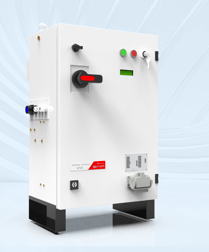
What you’re tryin’ to figure out
You’re standin’ at the bench, squintin’ at a stack of specs, and wonderin’ how a resistance welding controller differs from the rest of the system — and whether that lone meter on your cart is tellin’ you the truth. A resistance welding monitor reads signals and hands you data; the controller makes decisions; the system ties power, clamps, and timing together. I write this from years spent on the shop floor with quality techs and welders, so you’ll get straight talk, not fluff.
Terms you actually need to use
Terms get tossed around like rags. Here’s plain speak, with what each item does for you:- Resistance welding controller: the brain that times current, squeezes, welds and holds; it enforces the weld schedule.- Welding control system: the whole outfit — controller, power source, electrodes, safety interlocks, and communications.- Monitor: a device that measures outcome variables (current, force, energy) and logs them for quality checks.- Weld schedule: the set of parameters you run — squeeze time, weld current, weld time, hold time.- Adaptive control: when the controller adjusts parameters based on feedback, not just a fixed timer.When QA walks the line with a portable weld checker, they’re lookin’ at monitor readouts against the weld schedule to confirm the weld hit spec.
How these pieces talk on the line
You want reliable parts out the other end. Here’s how things behave together on the floor: the controller triggers the power source and timing; the power source supplies current; sensors feed a monitor or the controller with actual current and force; the monitor stores the proof for inspection. That chain’s only as strong as its weakest link. Folks often miss simple mismatches: electrode wear, loose cable lugs, or a bad ground will give false readings — but the monitor won’t lie if it’s set up right.
Common mistakes I’ve seen — and how to fix ’em
Been around enough to spot repeat offenders fast:- Treatin’ monitor readings as gospel without verifying sensor calibration. Check sensors monthly; verify with a known clamp or calibration jig.- Using a controller with no diagnostic outputs. Get one that spits out current and time data; you’ll save hours on root cause work.- Thinking a weld schedule is one-and-done. Teach operators to log deviations and review trends.- Ignoring mechanical wear. Replace electrodes before quality goes south.You won’t fix these with paperwork. You fix ’em by routin’ checks, simple tools, and spot audits on the bench.
Choosing tools that do the job — quick comparisons
Pick based on what you need on your floor, not what looks fancy:- Embedded analog controllers: simple, cheap, but limited diagnostics.- Digital controllers with logging: give you time-stamped events; good middle-ground.- PLC-based systems: flexible for complex lines; need an engineer to adjust.- Standalone monitors and portable checkers: quick field verification. I remember seeing portable weld checkers demoed at the International Manufacturing Technology Show (IMTS), side-by-side with production units — they make snagging bad welds fast and obvious.Match your choice to how much troubleshooting you want to do yourself and how often you inspect finished parts.
Final straight talk
If you’re fixin’ to tie controllers, monitors, and systems into a dependable operation, keep it simple: use a controller that reports clear diagnostics, verify monitors with routine checks, and make portable inspection part of your daily rhythm — that way you catch trouble before it becomes a recall. For practical alignment between controllers and monitoring hardware, many shops find solid, no-nonsense solutions from Sunke.